
Ray Boxes
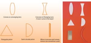
The shapes shown left are two dimensional representations of the apparatus shown on the right.
3.1 Lenses, Prisms and Mirrors
Ray boxes are frequently used with mirrors, glass or Perspex shapes. The pictures shown above are often used in student notes and work cards to
represent these shapes, as seen from above.
3.2 Using a Ray Box
Most ray boxes contain a 12 V fi lament bulb rated at around 24 W. However, laser and LED light sources are beginning to fi nd their way into schools but for the purposes of this course we will deal chiefl y with the fi lament bulb variety. These are connected to a 12 V supply and it is usual, though not essential, to use ac.
Safety warning!
The metal parts of a ray box can become quite
hot if it is switched on for any signifi cant length
of time.
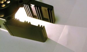
Figure 8. Ray box
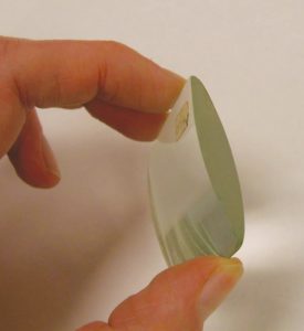
Figure 9. Cylindrical lens.
The light coming from the box on the left is not suitable for carrying out experiments. We usually want either one or more rays and often we want
the rays to be parallel, not diverging as the light is in the picture.
To make a parallel beam of light, we use a cylindrical lens similar to that shown above.
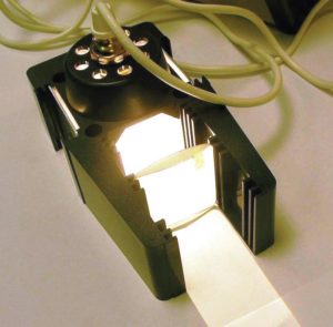
Figuyre 10. Ray box producing a parallel beam
The ray box shown above (figure 10) has a number of grooves into which the lens can be placed. Find the place where the lens makes the beam parallel as
shown.
In some ray boxes there may only be one fixed slot for the cylindrical lens but to obtain a parallel beam the position of the lamp is changed using a slider control.
Now put the slits in place.
If diverging rays are required, leave out the cylindrical lens (figure 13).
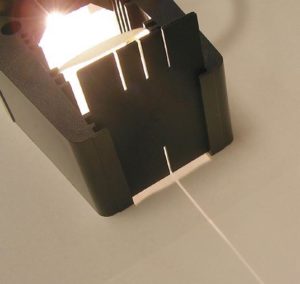
Figure 11. Raybox producing a single narrow beam of light
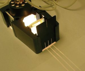
Figure 12. Raybox producing three parallel beams of light
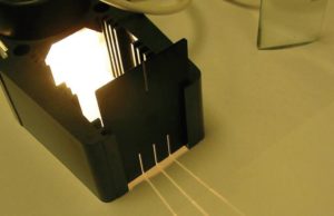
Figure 13. Raybox producing three diverging beams of light
3.3 Common Ray Box Applications
The pictures below show common ray box applications. To make the photographs clearer, a laser ray box was used in most cases.
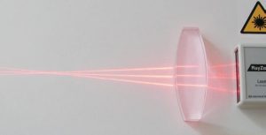
Figure 14. Laser Raybox with converging lens
Here (figure 14) a convex lens is bringing rays of light to a point of focus.
If the lens was more curved (often described in physics text books as “fatter”), the point of focus would be closer to the lens. If the ray box was set to give diverging rays, the point of focus would be further away.
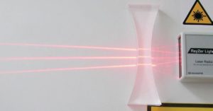
Figure 15. Laser Raybox with diverging lens
This is a concave or diverging lens (figure 15). Parallel rays from the ray box are made to spread out by the lens. What we are seeing in all these cases where light changes direction when going from one substance to another is a phenomenon called refraction.
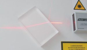
Figure 16 Refraction
Here (figure 16) a single ray enters a rectangular block. It emerges parallel to the direction it entered at. Note that some of the light is refl ected at the surface of the block. This always happens when light goes from one substance
to another, unless it enters “head on” at 90 degrees to the surface.
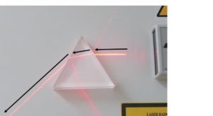
Figure 17 refraction
Red light is passed through a triangular prism. Try to follow the ray, ignoring refl ections.
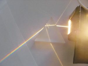
Figure 18. visible spectrum
White light follows the same path as the red light (figure 18) but it splits up into different colours, forming a visible spectrum. White light is a mixture of all colours but red light is a single colour so it does not split.
The experiment above is one of the most important, not to say beautiful ones, in physics. Here we are using a Perspex prism. More expensive glass prisms will give better spectra as will more sophisticated set-ups. See SSERC Bulletin 220 for details on how to produce the ultimate spectrum.
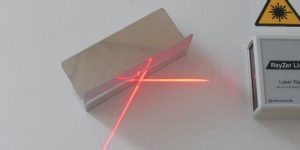
Figure 19. reflection
A single ray (figure 19) reflects from a plane (flat) mirror. It leaves the mirror at the same angle it struck it.
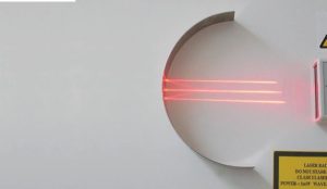
Figure 20. concave mirror
This concave mirror (figure 20) brings rays to a point of focus. Satellite dishes work in this way, concentrating weak signals from space on a single point.
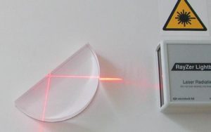
Figure 21. Total Internal reflection
Inside the glass block (figure 21), a special kind of reflection called Total Internal Reflection is taking place. The ray is striking the mid point of the semi-circular prism’s flat face.
3.4 Colour Mixing
Some companies now market colour mixers that use LEDs and SSERC also has a number of different designs that can be assembled by school technicians. Colour mixing can also be performed using ray boxes and filters.
The best results will be obtained using three ray boxes, one with a red, one with a blue and the third with a green filter in the slots where the slits usually go. Shine the ray boxes on to a white surface and make the colours overlap.
What you will see may surprise you if your experience of colour mixing has been limited to mixing paints. The kind of colour mixing that happens with ray boxes is called additive colour mixing.
Here is what you should see:
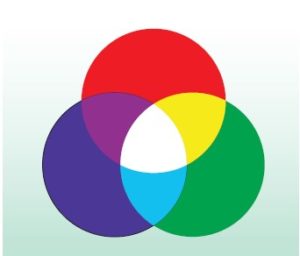
Figure 22. colour mixing
• Red + Blue = Magenta (purplish colour)
• Blue + Green = Cyan (turquoise)
• Red + Green = Yellow
• Red + Blue + Green = White
It can be diffi cult to get a pure white. Should this be the case, try altering the brightness of the individual colours – if each ray box has its own variable power supply.
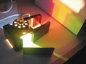
Figure 23. colour mixing using a single ray box
Some ray boxes are designed to be able to colour mix using a single ray box. Some require additional mirrors to do this, while others have the mirrors built in.
In the picture (figure 23) we see a ray box with a red filter in the front slots, a green filter on its right and a blue filter on its left. A mirror has been used to reflect the green light so that it overlaps with the red light, forming the colour yellow.
3.5 LED (Light Emitting Diode) Sources
SSERC Bulletins 212 and 220 give details on how to use bright white LEDs for school optics experiments. These can be effective replacements for ray boxes.
3.6 Lasers
Many schools have a laser that is used by teachers for demonstrations. A number of companies now make laser ray boxes. Please refer to Section 1 of
these notes: Basic Health and Safety in Physics for guidance on their use.