
Alpha Electronics Kit
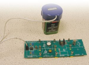
Figure 24. board powered by a battery
Alpha kit, which is used in schools to teach electronics, consists of boards and components that are built up to make circuits. The boards fit together using yellow links with screw fittings that are hand-tightened.
4.1 Power Supplies for Alpha Boards
Figure 24 shows a battery being used to power the boards, but other methods are possible and will be dealt with below.
Refer to the Power Supplies section for explanations of terms such as “smoothed” and “regulated”.
4.1.1 Regulated/Smoothed Power Supply
The power supply in figure 25 gives an unregulated, unsmoothed output. On its own this is unsuitable for use with Alpha kit and the board shown (figure 26) is used to smooth and regulate its output.
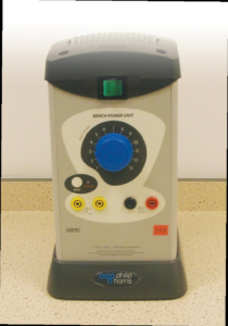
Figure 25. Power supply
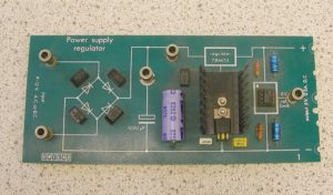
Figure 26. Electronic board
The leftmost sockets on the power supply shown (figure 27) provide a suitable output for Alpha kit but most schools use battery connector boards and 6 V batteries, as shown in figure 28.
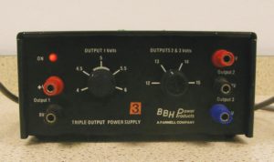
Figure 27. Suitable power supply
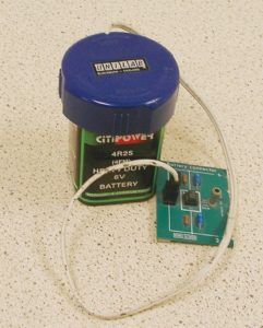
Figure 28. Battery connector board with 6V battery.
4.2 Joining Boards
To join boards together, slacken the screws on the yellow link shown in figure 29.
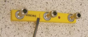
Figure 29. Joining link
Note: Links have a raised bit on them which matches a notch on the boards and care should be taken to ensure that the link is fitted the correct way round, with the raised bit in the notch. It is possible to join boards with the links connected the wrong way, but the circuit will not work.
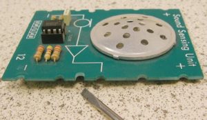
Figure 30. Board showing notch
When both boards are in place, tighten all three screws. The screws are not simply holding the boards together – they are also making electrical connections.

Figure 31. Board with link.
4.3 Fault Finding
There will be occasions when you are asked to set up a circuit and it doesn’t appear to work. The first thing to consider is, “Is it actually not working?”
Some circuits will only do something if it gets dark, cold or damp. For example, the circuit shown in figure 9 (page 18) would only light the bulb if it got dark. It therefore helps to know what a circuit is supposed to do before you build it.
4.3.1 Variable Resistor
Some circuits contain a variable resistor (figure 32) like the one in the picture. This may need to be adjusted for the circuit to work properly. For example, suppose that the light in the circuit shown in figure 24 comes on all the time. The variable resistor should be adjusted until the light goes off when the room is bright. The light should then come on when the light detector is covered.
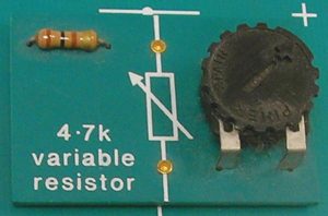
Figure 32. Variable resistor
4.3.2 Thermistor
A thermistor is a temperature-sensitive component that is used in circuits where a buzzer, light or motor has to be switched on when it gets hot.
Warm the thermistor by holding it between your finger and thumb, not by heating it with a Bunsen!
4.3.3 Connections
Most other faults are caused by slack links or by poorly connected batteries. All connections should be checked for tightness. In many cases, a circuit will work if the blue battery connector is removed and refitted.
4.3.4 Microchips
Faulty boards which have microchips (figure 33) fitted should be checked to ensure that the connecting pins of the microchip haven’t been damaged while being fitted. It’s not uncommon for pupils to remove microchips (more out of
curiosity than badness) and then damage the pins when trying to put them back in.
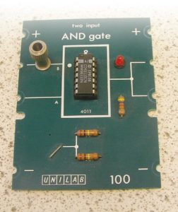
Figure 33. Board with microchip
4.3.5 Poorly Fitted Components
The board shown above (figure 34) has sockets cut out to allow components to be plugged in. These components do not always fit well and if a fault occurs when the circuit is built, the components should be moved gently from side to side to see if the circuit works temporarily.
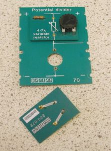
Figure 34. Board with comnent socket
4.3.6 Replacing Components
Substituting components or complete boards is a good fault finding technique. Start with the battery, then the blue battery connector, working your way through the circuit. The best way to check is to swap components one at a time from a circuit that is known to be working.
4.3.7 Fault Finding Using a Voltmeter
A voltmeter can be used as an aid to fault diagnosis. Start with it connected across the first yellow link in the circuit, as shown above. It should read just
over 6 V and this should not drop much below 6 V when the circuit is operated. If it does, check the battery. It should also remain fairly constant as you move from one link to another. There are more sophisticated fault finding techniques you can do using a voltmeter but they require more knowledge
of electronics than we are assuming here.
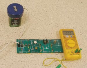
Figure 35. Fault finding using a meter.