
Meters
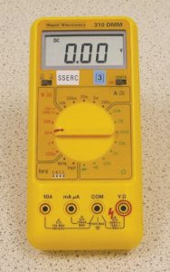
Figure 35. Multimeter.
5.1 Multimeter
The meter shown above (figure 35) is known as a multimeter. This is because it can be set to measure a number of different electrical quantities.
5.1.1 Current
Current is measured in Amperes (Amps or A for short) and is a measure of the flow of electric charge in a circuit.
5.1.2 Voltage
Sometimes referred to as potential difference or pd, voltage is a measure of the electrical pressure or “push” on charges. It is measured in volts (V).
5.1.3 Resistance
Resistance is a measure of how hard it is to make charges flow through a material – conducting material and insulating material. Conductors have
low resistances and insulators have high ones. Resistance is measured in ohms (Ω).
Most meters can be set to work with alternating current (ac) and direct current (dc).
See ‘Power Supplies’ section later for the difference between ac and dc.
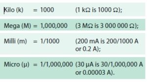
5.1.4 Kilo, Mega, milli, Micro
5.2 Measuring Current Using a Meter
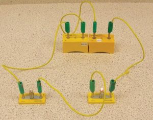
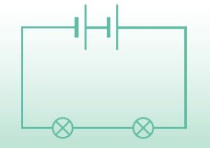
Figure 36. a. Series circuit & b. circuit diagram.
To measure the current in the above circuit (figure 36) there are 3 things that have to be done:
1) select the correct meter settings (figures 37 & 38);
2) use the correct sockets (figure 39);
3) connect the meter in the correct position in
the circuit.
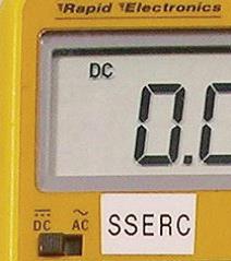
Figure 37. Switch with DC selected
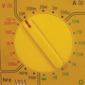
Figure 38. Selector dial set to 10A.
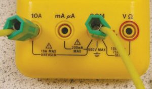
Figure 39. One lead in COM (commen) socket and other lead in the 10A socket.
Since the circuit is battery powered the current to be measured will be dc. The dc setting should be selected using the slide switch as shown (figure 37).
The meter shown has a slide switch to select dc or ac measurements but some meters have separate settings on the selector dial for ac and dc.
The dial is set to 10 A (figure 38) which is the greatest current that the meter can measure. If you are unsure of what range the current is likely to be in, it makes sense to start at the largest setting.
No matter what we are measuring, we will always have one lead in the COM (common) socket. In this case, the other lead goes in the 10 A socket (figure 39).
As current is a flow of charge we have to let the charge fl ow through the ammeter in order to measure it. To do this we have to break the circuit
and put the ammeter in the gap, using an extra lead to complete the circuit again.
This is described as “connecting in series”.
Notes
• If the reading on the meter is negative, you can make it read positive by swapping the leads around (i.e. put the lead that was in COM into 10 A and vice versa).
• If the reading on the meter is zero, or very small, try a more sensitive setting on the selector, e.g. 200 mA, but you will have to use the mA socket instead of the 10 A one. Disconnect the meter when changing settings.
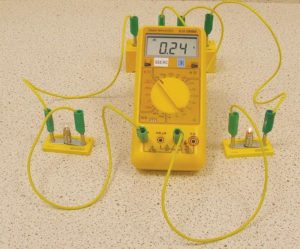
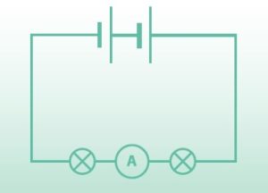
Figure 40. a. circuit for measuring current & b. circuit diagram.
• If a ‘1’ appears on the left hand side of the meter display, the reading is off the scale and you will have to select a less sensitive setting. This will not happen with the 10 A setting used with the circuit above.
• Some meters autorange; set the selector to ‘A’ and the best range will be selected automatically for you.
5.3 Measuring Voltage Using a Meter
If we want to measure the voltage (potential difference) across the left hand bulb in the above circuit (figure 40) we will once again have to consider the settings, sockets and meter position.
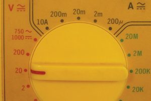
Figure 41. Selector dial set to 20V.
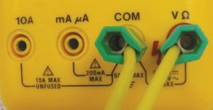
Figure 41. Leads connected to COM and V sockets.
The 20 V setting is a good bet for most classroom work. It is very unlikely that you would use a higher setting. Pupils are not allowed to work with voltages
over 33 V.
The ‘V’ and ‘COM’ sockets are always used when measuring voltage.
In this case we are measuring the voltage across a component. This gives us a clue as to how the voltmeter is connected. The circuit is not broken to connect the meter. Instead, the meter is connected across the bulb using stackable leads.
This is described as “connecting in parallel”.
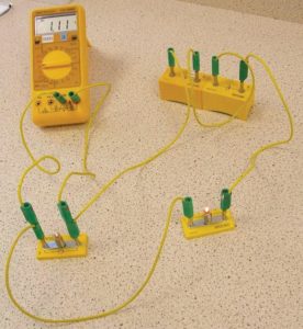
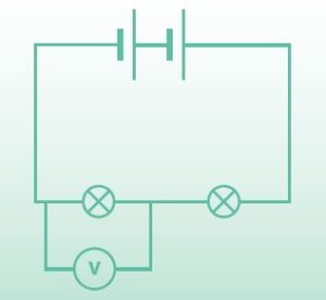
Figure 42. a. Circuit with meter connected for measuring voltage & b. circuit diagram.
5.4 Fault Finding Using a Meter
5.4.1 Checking the Power Supply
Suppose you have a circuit like the one above but connected to a power supply rather than batteries.
You are sure that you have wired it correctly and that the bulbs have the correct ratings but they do not light. How can you fi nd the fault?
Firstly, you could check the output from your power supply. Don’t assume that because the light is on in your power supply that it is actually working.
• Set your meter to 20 V;
• select ac or dc (this will depend on whether you are using the yellow or black and red sockets);
• connect ‘V’ and ‘COM’ to your power supply.
If the power supply is working, the meter should give a reading. The reading may not be exactly the same as your power supply selector dial claims but
an explanation for this can be found in the “Power Supplies” section.
Warning!
Do not attempt to measure mains voltages, HT or EHT voltages with this meter. Meters for measuring such voltages should be two-socket,
high impedance meters with probes to the standard outlined in HSE Guidance Note GS 38.
5.4.2 Fault Finding Using the Resistance Setting
The pictures below (figures 43/44) show the settings and sockets for using a multimeter to measure resistance. Used like this, the meter is very useful for identifying faulty components such as wires, switches and bulbs.
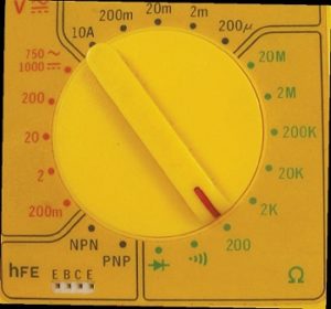
Figure 43. Selector dial set for measuring resistance.
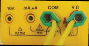
Figure 44. Connections used for measuring resistance.
Warning!
When testing wires, bulbs, etc. with a resistance meter, they must be removed from the circuit.
Also, do not test batteries with a meter that has been set to measure resistance. Use the voltage setting instead.
a) Testing Connecting Wires
Connecting wires should have a low resistance (e.g. 0.1 Ω or so) as shown in figure 45.
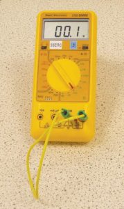
Figure 45. Meter display showing typical resistance of a good lead.
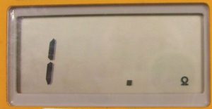
Figure 46. Meter displaying an ‘open circuit’ fault.
When testing a wire it should be connected from the ‘COM’ socket to the ‘Ω’ socket. If you get a reading like the one shown above (figure 46), the wire is faulty (usually a break somewhere along its length). This fault is known as an ‘open circuit’.
b) Testing Bulbs
Bulbs can also be tested using a meter and should have a resistance of a few ohms (as shown in figure 47). If you get an open circuit reading, like the one above, either the bulb (or its holder) is faulty. In such cases the bulb should be checked to ensure that it is properly screwed in!
Occasionally, a bulb will fail to light and have a much lower resistance than it should (about the same as the resistance of a wire). This fault is known as a ‘short circuit’.
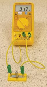
Figure 47. Testing a bulb using a meter.
c) Testing Switches
Switches should have a very low resistance when they are switched on and an open circuit resistance when they are off.