Oscilloscopes
Oscilloscopes are used for examining electrical signals. In schools, they are often connected to signal generators, microphones and power supplies, usually to show pupils the difference between ac and dc.
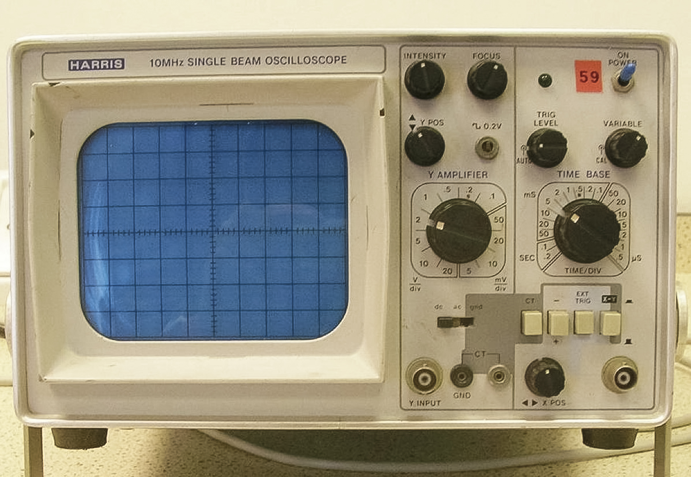
Figure 48. Typical oscilloscope
6.1 Getting a Trace
The following instructions assume that you are going to connect a working signal generator to the oscilloscope (signal generators are covered
in section 8).
• Don’t connect anything to the oscilloscope initially;
• Plug in the oscilloscope;
• Switch the oscilloscope on (note that on some models, the switch is on the back);
• Wait. Like old television sets, some oscilloscopes need time to “warm-up”.
Before connecting anything to the oscilloscope, you should try to get a horizontal line across the middle of the screen (this is shown in the video).
The line that appears on the screen is referred to as the trace. A line will possibly appear on your screen or you may see a dot move across it. If you do not see anything, try the following in the order shown:
• Locate the control marked trig level and turn it to auto;
• Turn up the brightness control;
• Adjust the x pos or x shift controls and the y pos or y shift controls. The trace may actually be lying off the screen and these controls move it left and right (x) or up and down (y) to bring it into view;
• If the trace appears as a splodge rather than a sharp dot or line, adjust the focus control and turn down the brightness.
The signal generator can now be connected to the Y input socket and switched on. It should be noted that, while many oscilloscopes have BNC sockets, some have 4 mm sockets.
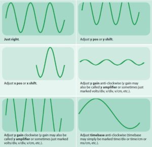
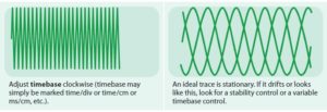
The illustrations below show the desired wave pattern that should be seen on the screen and the adjustments that have to be made in order to achieve this.