
Light Gates and Timers
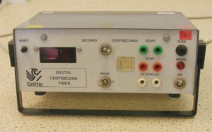
Figure 1: Electronic timer.
2.1 Electronic Timers
Physics pupils are often asked to calculate speed by measuring a distance and fi nding the time tocover that distance. Speed is found by dividing distance by time. Stopwatches are fi ne for times of around fi ve seconds or more, but because of human reaction time they are no use for short times. In such cases, we use timers that can be started and stopped electronically.
2.2 Light Gates
The most common way of starting and stopping a timer is to use a light gate.
On the right is a light source, pointing at a light detector. The source is connected to a power supply (timers such as the one shown in fi gure 1
have a built-in power supply for light sources – note the 2 V 0.5 A sockets). The detector is connected to the START or STOP sockets. Picture a beam of light
going from the source to the detector. Breaking the beam starts or stops the timer. The beauty of this arrangement is that there is no human reaction
time to affect the measurement of time. Also, the object whose time you are measuring is not slowed down when passing through the beam. If you are
measuring the speed of a trolley, it has to be fi tted with a “mask” to cut the light beam.
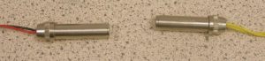
Figure 2. Light Gate
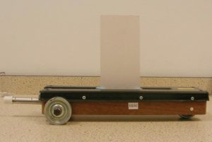
Figure 3. Trolley with a mask
2.3 Timing Using Light Gates
2.3.1 Average Speed
The light gates shown in figure 2 are mounted on a clamp stand with the source on one side of a trolley ramp and the detector on the other. They
can be difficult to line up and some manufacturers make light gates with the source and detector in a single unit. One such device is shown below.
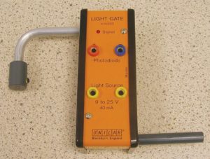
Figure 4. Combined light source and detector. The Photodiode is the light detector.
The diagram on the next page shows a typical set-up to measure the average speed of a trolley going down a slope.
The teacher or pupils will measure the distance between the light gates. It makes sense to put them a memorable distance apart, e.g. 50 cm, 100 cm,
measuring from the same point on each gate.
Light Gates and Timers
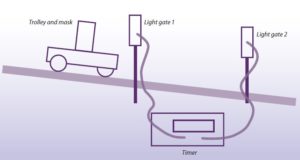
Figure 5 – Measuring average speed using two light gates.
- Connect light gate 1 to the start sockets of the timer;
- Connect light gate 2 to the stop sockets.
Each light gate’s light source needs to be connected to a suitable power supply unless the light gate is battery operated. Some timers, as mentioned previously, have sockets for light sources. - Pass your hand through light gate 1. The timer should start. It should stop when you pass your hand through light gate 2. If this doesn’t happen, or if the timer runs without stopping as soon as you connect things, try the following:
– Are the lights in the sources on?
– Are they bright? If not, you may be using the wrong power supply voltage.
– Have you accidentally connected the detectors to the power supply instead of the sources? Try swapping the detector leads around (black where red was, for example)
– Switch the timer off
– Switch it back on and try again
– If the timer has a mode switch (usually “mode 1/2”), try a different setting
– Substitute a different light gate. - Once the timer starts and stops properly, check that the trolley runs freely down the slope and that the mask cuts both beams without hitting against any of the equipment.
- Reset the timer to zero.
2.3.2 Instantaneous Speed
The previous experiment showed how to measure the average speed of a trolley as it ran down a ramp. However, if we want to measure the speed at a
particular point (the instantaneous speed) the last experiment would be of no use because the speed of the trolley would be changing all the time – slow
at the fi rst light gate, faster at the second.
To get the instantaneous speed, the average speed over a short distance has to be measured since the speed does not have much chance to change over
a short distance. It could be possible to do this by putting the light gates closer together; but there is a much better way (see fi gure 6). It involves using one light gate only and a mask of known width. The timer is set to start when the beam is broken and stop when it is restored, i.e. when the mask comes out of the light gate.
The speed is calculated by dividing the length of the card by the time on the timer. If setting this up, make the mask length something like 4 cm or 5 cm
rather than 3.4567 cm!
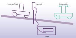
Figure 6. Measuring instantaneous speed with a single light gate
How you set the timer up depends on the model of timer. Ask around or look at the video for examples.
To check this set-up, put your hand in the beam. The timer should run for as long as the beam is blocked out.
2.3.3 Timers with Built-in Microprocessors
Figure 7 (below) shows two devices used in many schools- the Unilab QED (background) and the DJB TSA (foreground).
They are timers with built-in processors. They can record more than one time and, if you enter the width of the mask into them, can calculate speed
and acceleration.
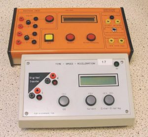
Figure 7. Timers with built in microprocessors
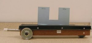
Figure 8. Trolley with a double mask.
2.3.4 Trolley with Double Mask
If using timers like those shown in fi gure 7 and a single light gate to find acceleration, you will need to fi t your trolley with a double mask (fi gure 8).
This is because acceleration is found from 2 speeds and the time it takes to get from one speed to another. Each of the two parts of the mask has to
be the same width but the width of the gap is not important.