
Signal Generators
8.1 Types and Common Uses
Signal generators are mostly used in schools to connect them to loudspeakers to produce a variety of sounds. They may also be used with oscilloscopes to look at the electrical signals associated with sounds.
As can be seen from the picture below (figure 53), there are a number of different kinds of signal generator in use in schools.
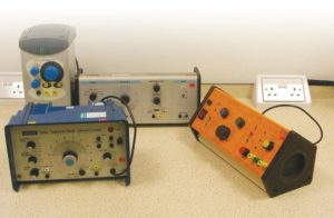
Figure 53. Selection of signal generators.
8.2 Common Controls
Although there are many kinds of signal generators, they all have certain controls in common. The main ones are shown below (figure 54).
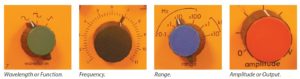
Figure 54. Signal generator controls
8.3 Attenuator Control
In addition, signal generators may have an Attenuator Control (figure 55). For the purposes of the following exercise we will leave this set to ‘0’ (or
‘1’ or ‘÷1’ depending on the model being used).
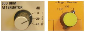
Figure 55. Attenuator controls.
8.4 Connecting a Loudspeaker
• Turn the Waveform control to: ~
• Turn the range control to: x100 Hz (not kHz)
• Turn the frequency control to: 2 or 3 (it isn’t vital exactly where).
• Turn the amplitude control right down.
• Connect your loudspeaker to the sockets.
Note
Some signal generators may have three sockets as shown below (figure 56).
The green socket and the one marked ‘Lo’ are used for connecting a loudspeaker.
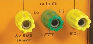
Figure 56. Loud speaker sockets.
Others may have two pairs of sockets. In this case, the ones marked “amplified output” or “power output” should be used.
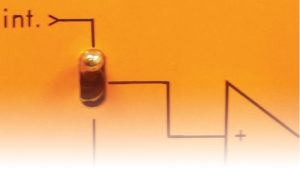
Figure 57. Switch (Unilab).
Signal generators without amplifiers will still be able to drive small loudspeakers.
Switch the signal generator on (note that older ones will have a significant “warm up” time).
Slowly bring the amplitude control up and you should hear a sound that gets louder as you increase the amplitude. If you are using a Unilab signal generator and can’t hear anything, check that the switch, shown in figure 57, is in the position shown.
To see an oscilloscope trace, connect the oscilloscope across the same sockets as the loudspeaker. If stackable leads have been used (i.e. leads you can plug another lead into), it is possible to have both connected at the same
time. This is a common set-up in physics classes.
For instructions on setting up the oscilloscope, see section 6. Note that your oscilloscope sockets may be red and black rather than yellow and green.
In general, matching black to green will work.
8.5 Signal Generator Controls
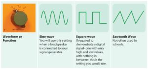
Figure 58. Waveform or Function controls.
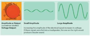
Figure 59. Amplitude or Output controls.
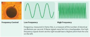
Figure 60. Frequency Control.
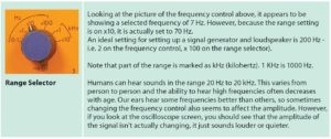
Figure 61. Range selection control.